Quantcast
Channel: How To - Labnario
Viewing all 36 articles
Browse latest View live

disabling Huawei S3300 notification record

$
0
0

In this post I will show you how to disable a notification record which appears always after you type a configuration command. This notification causes your frustration when you want to configure anything on this switch and suddenly you see the following record:

[labnario]interface GigabitEthernet 0/0/1
[labnario-GigabitEthernet0/0/1]
Jan  1 2008 00:24:47+01:00 labnario DS/4/DATASYNC_CFGCHANGE:OID 1.3.6.1.4.1.2011.5.25.191.3.1 configurations have been changed. The current change number is 24, the change loop count is 0, and the maximum number of records is 4095.

You have such situation on Huawei S2300, S3300 and S5300 switches if you are logged by the console.

How to cope with it?

You have two ways to do this. The first is to disable it temporarily by the following commands:

<labnario>undo terminal monitor

or

<labnario>undo terminal trapping

The only disadvantage of the temporary solution is that after you are logged by the console once again this notification still exists. At the same time you block all notifications in the console view.

The second solution is to disable this notification in info-center of the switch:

[labnario]info-center source DS channel console trap state off level warnings

How to find appropriate parameters for this command?

You can find all needed information from this notification:

Jan  1 2008 00:24:47+01:00 labnario DS/4/DATASYNC_CFGCHANGE:OID 1.3.6.1.4.1.2011.5.25.191.3.1 configurations have been changed. The current change number is 24, the change loop count is 0, and the maximum number of records is 4095.

Source: DS
Level: 4 (warnings)
Channel: console.


screen length of terminal

$
0
0

24 – the default number of lines on one screen

<NE40E> display current-configuration
#
 sysname NE40E
#
 super password level 1 simple huawei1
 super password level 3 simple huawei
 super password level 15 simple labnario
#
 FTP server enable
 FTP acl 2000
#
 info-center source BFD channel 1 log level informational
 info-center loghost source GigabitEthernet0/0/0
 info-center loghost 172.16.20.90 facility local4
#
 vlan batch 31 to 32 98 100
#
 hotkey CTRL_U "display ip interface brief"
#
 undo cluster enable
#
snmp-agent trap type base-trap
#
 load-balance ip-enhance all
  ---- More ----

How to change it?

[NE40E]user-interface vty 0 4
[NE40E-ui-vty0-4]screen-length 0

The value is an integer ranging from 0 to 512. 0 indicates the split screen is disabled (it is useful when you want to use scripts).

If you want to change screen length only for the current terminal, use temporary option in the above command. It is valid only for the active user interface till the user leaves.

[NE40E]user-interface vty 0 4
[NE40E-ui-vty0-4]screen-length 60 temporary
Info: The configuration takes effect on the current user terminal interface only.

how to delete a telnet user

$
0
0

Sometimes we can meet such situation on a router or a switch:

 [labnario]display users
  User-Intf    Delay    Type   Network Address     AuthenStatus    AuthorcmdFlag
+ 34  VTY 0   00:00:00  TEL    172.29.12.226             pass           no      Username : huawei
  35  VTY 1   00:08:01  TEL    172.29.12.226             pass           no      Username : labnario
  36  VTY 2   00:07:38  TEL    172.29.12.226             pass           no      Username : killer
  37  VTY 3   00:07:00  TEL    172.29.12.226             pass           no      Username : killer
  38  VTY 4   00:01:34  TEL    172.29.12.226             pass           no      Username : labnario

By default, on Huawei device, there are 5 vty lines available. If all these lines are occupied by users, no other user is able to access the device. Such situation can appear in 2 cases:

  1. The device is fully occupied by telnet users.
  2. All telnet sessions are hang.

The first case is normal and it can often happen. Sessions will be deleted when users log out from the device or their sessions’ idle-timeout expires. By default idle-timeout is set to 10 minutes.

The second case can be caused by idle-timeout of vty lines set to 0:

#
user-interface vty 0 4
 authentication-mode aaa
 idle-timeout 0 0
#

It means that this session never expires. If a user forget to log out from a device, vty line is still being occupied. This causes that a next user has no possibility to telnet the device.

If you have access by console port or you are already logged in by telnet, you can delete all unnecessary telnet sessions:

<labnario>free user-interface vty 4
Warning: User interface VTY4 will be freed. Continue? [Y/N]:y
 [OK]
<labnario>display users
  User-Intf    Delay    Type   Network Address     AuthenStatus    AuthorcmdFlag
+ 34  VTY 0   00:00:00  TEL    172.29.12.226             pass           no      Username : huawei
  35  VTY 1   00:13:14  TEL    172.29.12.226             pass           no      Username : labnario
  36  VTY 2   00:12:51  TEL    172.29.12.226             pass           no      Username : killer
  37  VTY 3   00:12:13  TEL    172.29.12.226             pass           no      Username : killer

To avoid such situation, configure idle-timout for vty lines different than 0:

#
user-interface vty 0 4
 authentication-mode aaa
 idle-timeout 15 0
#

You can also set maximum-vty sessions to 15 and configure the same parameters for all vty lines:

[labnario]user-interface maximum-vty 15 
[labnario]user-interface vty 0 14
 authentication-mode aaa
 idle-timeout 15 0

Now you have 16 vty lines available.

how to configure multiple interfaces at the same time

$
0
0

This is an useful feature, specially if we want to configure Huawei’s switch, where there are lots of physical interfaces. Very often, some of interfaces have the same configuration. Instead of configure the interfaces one by one it is easier to configure multiple interfaces at the same time. It improves the efficiency.

Let’s assume that you want to add 5 GE interfaces to VLAN 100:

[labnario]port-group labnario
[labnario-port-group-labnario]group-member GigabitEthernet 0/0/1 to GigabitEthernet 0/0/5
[labnario-port-group-labnario]port link-type access
[labnario-port-group-labnario]port default vlan 100

[labnario]dis cur | beg port-group
port-group labnario
 group-member GigabitEthernet0/0/1
 group-member GigabitEthernet0/0/2
 group-member GigabitEthernet0/0/3
 group-member GigabitEthernet0/0/4
 group-member GigabitEthernet0/0/5

[labnario-port-group-labnario]dis cur interface gig
#
interface GigabitEthernet0/0/1
 port link-type access
 port default vlan 100
#
interface GigabitEthernet0/0/2
 port link-type access
 port default vlan 100
#
interface GigabitEthernet0/0/3
 port link-type access
 port default vlan 100
#
interface GigabitEthernet0/0/4
 port link-type access
 port default vlan 100
#
interface GigabitEthernet0/0/5
 port link-type access
 port default vlan 100
...
[labnario]display port-group all
Portgroup: labnario
GigabitEthernet0/0/1
GigabitEthernet0/0/2
GigabitEthernet0/0/3
GigabitEthernet0/0/4
GigabitEthernet0/0/5

Note that only physical interfaces of the same board can be added to an interface group.

how to check the default configuration of switch’s interface

$
0
0

When taking into consideration that default settings are invisible in a configuration file, it is a good information that Huawei’s S3700/S5700 switches have such possibility to display default settings for ethernet interfaces. The ‘display this include-default’ command displays the effective configurations in the current view, including the unchanged default configurations.

[labnario-Ethernet0/0/1]display this include-default 
#
interface Ethernet0/0/1
 portswitch
 undo shutdown
 enable snmp trap updown
 undo set flow-stat interval
 undo qinq vlan-translation enable
 undo mac-address learning disable
 port priority 0
 port link-type hybrid
 port hybrid pvid vlan 1
 port hybrid untagged vlan 1
 qinq protocol 8100
 undo loopback-detect enable
 stp enable
 undo stp config-digest-snoop
 undo stp no-agreement-check
 undo stp root-protection
 undo stp loop-protection
 stp transmit-limit 147
 stp point-to-point auto
 stp compliance auto

 stp instance 0 port priority 128
 undo port mux-vlan enable
 undo mac-vlan enable
 undo ip-subnet-vlan enable
 undo rmon-statistics
 undo smart-link flush receive
 undo smart-link vll-notify enable
 undo ntdp enable
 undo ndp enable
 bpdu enable
 undo portal local-server enable
 undo dot1x enable
 dot1x max-user 256
 dot1x port-control auto
 dot1x port-method mac
 undo dot1x reauthenticate
 undo authentication critical eapol-success
 authentication max-reauth-req 20
 undo mac-authen
 mac-authen max-user 256
 mac-authen reauthenticate
 undo authentication open
 undo port-auto-sleep enable
 undo port-security enable
 undo qinq vlan-translation miss-drop
 undo port discard tagged-packet
 mac-learning priority 0
 undo mac-address flapping trigger error-down
 undo mac-address flapping trigger quit-vlan
 jumboframe enable 9216
 undo set flow-statistics include-interframe
 trap-threshold input-rate 100 resume-rate 100
 trap-threshold output-rate 100 resume-rate 100
 log-threshold input-rate 100 resume-rate 100
 log-threshold output-rate 100 resume-rate 100
 trap-threshold error-statistics 3 interval 10
 carrier up-hold-time 2000
 carrier down-hold-time 0
 undo port link-flap protection enable
 qos wrr
 qos queue 0 wrr weight 1
 qos queue 1 wrr weight 1
 qos queue 2 wrr weight 1
 qos queue 3 wrr weight 1
 qos queue 4 wrr weight 1
 qos queue 5 wrr weight 1
 qos queue 6 wrr weight 1
 qos queue 7 wrr weight 1
 trust 8021p outer
 undo dei enable
 qos phb marking enable
 undo arp anti-attack rate-limit enable
 undo arp-miss anti-attack rate-limit enable
 undo arp anti-attack check user-bind enable
 undo ip source check user-bind enable
 unicast-suppression 100
 multicast-suppression 100
 broadcast-suppression 100
 storm-control interval 5
 port type nni
 undo nd snooping enable
 undo nd snooping trusted
 undo dhcpv6 remote-id insert enable
 undo dhcpv6 remote-id rebuild enable

This command is supported in V100R006C03 and V200R001 software versions.

Let’s add some configuration to the interface:

[labnario-Ethernet0/0/1]display this
#
interface Ethernet0/0/1
#
return
[labnario-Ethernet0/0/1]port link-type access 
[labnario-Ethernet0/0/1]port default vlan 100
[labnario-Ethernet0/0/1]display this
#
interface Ethernet0/0/1
 port link-type access
 port default vlan 100
#
return

Now use ‘display this include-default‘ command again:

[labnario-Ethernet0/0/1]dis th include-default 
#
interface Ethernet0/0/1
 portswitch
 undo shutdown
 enable snmp trap updown
 undo set flow-stat interval
 undo qinq vlan-translation enable
 undo mac-address learning disable
 port priority 0
 port link-type access
 port default vlan 100
 qinq protocol 8100
 undo loopback-detect enable
 stp enable
 undo stp config-digest-snoop
 undo stp no-agreement-check
 undo stp root-protection
 undo stp loop-protection
 stp transmit-limit 147
 stp point-to-point auto
 stp compliance auto
 stp instance 0 port priority 128
 undo port mux-vlan enable
 undo mac-vlan enable
 undo ip-subnet-vlan enable
 undo rmon-statistics
 undo smart-link flush receive
 undo smart-link vll-notify enable
 undo ntdp enable
 undo ndp enable
 bpdu enable
 undo portal local-server enable
 undo dot1x enable
 dot1x max-user 256
 dot1x port-control auto
 dot1x port-method mac
 undo dot1x reauthenticate
 undo authentication critical eapol-success
 authentication max-reauth-req 20
 undo mac-authen
 mac-authen max-user 256
 mac-authen reauthenticate
 undo authentication open
 undo port-auto-sleep enable
 undo port-security enable
 undo qinq vlan-translation miss-drop
 undo port discard tagged-packet
 mac-learning priority 0
 undo mac-address flapping trigger error-down
 undo mac-address flapping trigger quit-vlan
 jumboframe enable 9216
 undo set flow-statistics include-interframe
 trap-threshold input-rate 100 resume-rate 100
 trap-threshold output-rate 100 resume-rate 100
 log-threshold input-rate 100 resume-rate 100
 log-threshold output-rate 100 resume-rate 100
 trap-threshold error-statistics 3 interval 10
 carrier up-hold-time 2000
 carrier down-hold-time 0
 undo port link-flap protection enable
 qos wrr
 qos queue 0 wrr weight 1
 qos queue 1 wrr weight 1
 qos queue 2 wrr weight 1
 qos queue 3 wrr weight 1
 qos queue 4 wrr weight 1
 qos queue 5 wrr weight 1
 qos queue 6 wrr weight 1
 qos queue 7 wrr weight 1
 trust 8021p outer
 undo dei enable
 qos phb marking enable
 undo arp anti-attack rate-limit enable
 undo arp-miss anti-attack rate-limit enable
 undo arp anti-attack check user-bind enable
 undo ip source check user-bind enable
 unicast-suppression 100
 multicast-suppression 100
 broadcast-suppression 100
 storm-control interval 5
 port type nni
 undo nd snooping enable
 undo nd snooping trusted
 undo dhcpv6 remote-id insert enable
 undo dhcpv6 remote-id rebuild enable
#
return

As you can see, the command shows both manually configured and default settings.

What if you want to come back to the previous settings (default):

  • Delete configuration one by one:
[labnario-Ethernet0/0/1]undo port default vlan 
[labnario-Ethernet0/0/1]undo port link-type
  • Perform one-touch configuration clearance on an interface:
[labnario]clear configuration interface Ethernet 0/0/1 
Warning: All configurations of the interface will be cleared, and its state will
 be shutdown. Continue? [Y/N] :y
Info: Total execute 2 command(s), 2 successful, 0 failed.

[labnario]dis cu int eth 0/0/1
#
interface Ethernet0/0/1
 shutdown
#
return

All configuration has been deleted. Note that interface went to ‘shutdown‘ state.

19 Nov 2012 how to display power of optical module

$
0
0

Let’s take Huawei’s S3328TP-SI switch as an example. This switch has 2 combo ports, which can be changed either to optical or electrical mode.

[Quidway]display elabel
...
[Board Properties]
BoardType=CX5Z228AM
BarCode=21023513816TA9000116
Item=02351381
Description=Quidway S3328TP-SI,CX5Z228AM,S3328TP-SI Mainframe(24 10/100 BASE-T ports and 2 Combo GE(10/100/1000 BASE-T+100/1000 Base-X) ports and 2 SFP GE (1000 BASE-X) ports (SFP Req.) and AC 110/220V)
Manufactured=2010-09-28
VendorName=Huawei
IssueNumber=
CLEICode=
BOM=
...

Use ‘display interface …” command to check port mode of the interface:

[Quidway]display interface GigabitEthernet 0/0/4
GigabitEthernet0/0/4 current state : UP
Line protocol current state : UP
Description:HUAWEI, Quidway Series, GigabitEthernet0/0/4 Interface
Switch Port,PVID :    1,The Maximum Frame Length is 1600
IP Sending Frames' Format is PKTFMT_ETHNT_2, Hardware address is 286e-d49b-8c17
Port Mode: COMBO AUTO
Current Work Mode: FIBER
Speed : 1000,  Loopback: PHY
Duplex: FULL,  Negotiation: DISABLE
Last 300 seconds input rate 0 bits/sec, 0 packets/sec
Last 300 seconds output rate 0 bits/sec, 0 packets/sec
Input peak rate 0 bits/sec,Record time: -
Output peak rate 0 bits/sec,Record time: -
Input:  0 packets, 0 bytes
Unicast        :                   0,Multicast          :                   0
Broadcast      :                   0,Jumbo              :                   0
CRC            :                   0,Giants             :                   0
Jabbers        :                   0,Throttles          :                   0
Runts          :                   0,DropEvents         :                   0
Alignments     :                   0,Symbols            :                   0
Ignoreds       :                   0,Frames             :                   0
Discard        :                   0,Total Error        :                   0
Output:  0 packets, 0 bytes
Unicast        :                   0,Multicast          :                   0
Broadcast      :                   0,Jumbo              :                   0
Collisions     :                   0,Deferreds          :                   0
Late Collisions:                   0,ExcessiveCollisions:                   0
Buffers Purged :                   0
Discard        :                   0,Total Error        :                   0
    Input bandwidth utilization threshold : 100.00%
    Output bandwidth utilization threshold: 100.00%
    Input bandwidth utilization  : 0.00%
    Output bandwidth utilization : 0.00%

You have 3 options in combo-port command:

  • auto – selects the interface type automatically
  • copper – uses the electrical interface
  • fiber – uses the optical interface.

As you can see in the above output, port mode is COMBO AUTO, SFP module has been inserted and current work mode is automatically chosen as FIBER.

To display optical power of SFP module:
[Quidway]display transceiver interface GigabitEthernet 0/0/4 verbose

GigabitEthernet0/0/4 transceiver information:
-------------------------------------------------------------
Common information:
  Transceiver Type               :OC48_SHORT_REACH_SFP
  Connector Type                 :LC
  Wavelength(nm)                 :1310
  Transfer Distance(m)           :5000(90um)
  Digital Diagnostic Monitoring  :YES
  Vendor Name                    :FINISAR CORP.
  Ordering Name                  :
-------------------------------------------------------------
Manufacture information:
  Manu. Serial Number            :'P6R282H
  Manufacturing Date             :2004-12-18
  Vendor Name                    :FINISAR CORP.
-------------------------------------------------------------
Diagnostic information:
  Temperature(ĄăC)              :44.00
  Temp High Threshold(ĄăC)      :93.00
  Temp Low  Threshold(ĄăC)      :-30.00
  Voltage(V)                    :3.30
  Volt High Threshold(V)        :3.70
  Volt Low  Threshold(V)        :2.90
  Bias Current(mA)              :25.76
  Bias High Threshold(mA)       :70.00
  Bias Low  Threshold(mA)       :4.00
  RX Power(dBM)                 :-33.69
  RX Power High Threshold(dBM)  :-1.00
  RX Power Low  Threshold(dBM)  :-20.00
  TX Power(dBM)                 :-6.14
  TX Power High Threshold(dBM)  :-1.02
  TX Power Low  Threshold(dBM)  :-11.52
-------------------------------------------------------------

Verbose option displays detailed information about the optical module, including the basic information, manufacturing information, alarm information and diagnosis information.

how to configure trunk between Huawei router and switch

$
0
0

What we want to do is to configure 802.1q trunk between labnario1 router and labnarioSW1 switch, so that hosts from VLAN 100 will be able to ping the router’s interface.

Let’s look at the simple topology:

First we want to configure labnario1 router. To configure Ge0/0/1 interface to operate as a 802.1q trunk, we need to configure it as follows:

<labnario1>system-view
[labnario1]
[labnario1]interface GigabitEthernet 0/0/1
[labnario1-GigabitEthernet0/0/1]portswitch
[labnario1-GigabitEthernet0/0/1]port link-type trunk

Now we need to configure subinterface in VLAN 100 and define IP address. Of course our subinterface should be in the same VLAN as our hosts.

[labnario1]interface GigabitEthernet0/0/1.100
[labnario1-GigabitEthernet0/0/1.100]vlan-type dot1q 100
[labnario1-GigabitEthernet0/0/1.100]ip address 150.100.0.1 255.255.255.0

Labnario1 router configuration is finished. Now we can start configuring labnarioSW1 switch. Let’s start with 802.1q trunk configuration:

<labnario1>sys
[LabnarioSW1]
[LabnarioSW1]int GigabitEthernet 0/0/1
[LabnarioSW1-GigabitEthernet0/0/1]port link-type trunk
[LabnarioSW1-GigabitEthernet0/0/1]port trunk allow-pass vlan 100

Now we can add our hosts to VLAN 100:

[LabnarioSW1]interface Ethernet0/0/1
[LabnarioSW1-Ethernet0/0/1]port link-type access
[LabnarioSW1-Ethernet0/0/1] port default vlan 100
[LabnarioSW1]interface Ethernet0/0/2
[LabnarioSW1-Ethernet0/0/1]port link-type access
[LabnarioSW1-Ethernet0/0/1] port default vlan 100

As a last part of this configuration we need to add VLANIF interface on labnarioSW1:

[LabnarioSW1-Ethernet0/0/1]int vlanif100
[LabnarioSW1-Vlanif100]ip add 150.100.0.2 255.255.255.0

Both devices are configured. Let’s check if our hosts are able to ping router’s interface:

PC1>ping 150.100.0.2

Ping 150.100.0.2: 32 data bytes, Press Ctrl_C to break
From 150.100.0.2: bytes=32 seq=1 ttl=255 time=16 ms
From 150.100.0.2: bytes=32 seq=2 ttl=255 time=15 ms
From 150.100.0.2: bytes=32 seq=3 ttl=255 time=16 ms
From 150.100.0.2: bytes=32 seq=4 ttl=255 time=16 ms
From 150.100.0.2: bytes=32 seq=5 ttl=255 time=15 ms

--- 150.100.0.2 ping statistics ---
  5 packet(s) transmitted
  5 packet(s) received
  0.00% packet loss
  round-trip min/avg/max = 0/12/16 ms

PC2>ping 150.100.0.1

Ping 150.100.0.1: 32 data bytes, Press Ctrl_C to break
From 150.100.0.1: bytes=32 seq=1 ttl=255 time=16 ms
From 150.100.0.1: bytes=32 seq=2 ttl=255 time=78 ms
From 150.100.0.1: bytes=32 seq=3 ttl=255 time=47 ms
From 150.100.0.1: bytes=32 seq=4 ttl=255 time=16 ms
From 150.100.0.1: bytes=32 seq=5 ttl=255 time=47 ms

--- 150.100.0.1 ping statistics ---
  5 packet(s) transmitted
  5 packet(s) received
  0.00% packet loss
  round-trip min/avg/max = 16/40/78 ms

how to find TC packets source on Huawei switch

$
0
0

Topology Change (TC) packets are sent when MSTP-enabled interface in a network flaps. If a physical interface frequently alternates between Up and Down, the MSTP status of the device in the network becomes unsteady. As a result, a large number of TC messages are generated, ARP entries are frequently deleted and services are interrupted.

How to find the source of TC packets?

Let’s look at the log, generated on one of the switches in a network. Let’s take Huawei S9300 switch as an example:

Dec 19 2012 11:32:56+10:00 S9300 %%01MSTP/6/RECEIVE_MSTITC(l)[40922]:MSTP received BPDU with TC, MSTP process 0 instance 0, port name is GigabitEthernet6/0/0.

What can we find in this log?

The most important for us is the port number on which the switch received TC packet, in this case interface GE6/0/0. To troubleshoot this problem we have to go to the next switch, connected to interface GE6/0/0 and check logs of that switch. If the neighbouring switch receives TC packets as well, we have to do further troubleshooting. If we find in the logs that MSTP-enabled interface is flapping, we can consider that this interface is the source of the TC packet. If this interface is still flapping, just make it down, to avoid unsteady behaviour.

To check whether the device has received TC messages:

[S9300] display stp 
-------[CIST Global Info][Mode MSTP]-------
CIST Bridge         :57344.00e0-fc00-1597
Bridge Times        :Hello 2s MaxAge 20s FwDly 15s MaxHop 20
CIST Root/ERPC      :0    .0018-826f-fc7a / 20000
CIST RegRoot/IRPC   :57344.00e0-fc00-1597 / 0
CIST RootPortId     :128.2
BPDU-Protection     :disabled
TC or TCN received  :0
TC count per hello  :0
STP Converge Mode   :Nomal
Time since last TC :2 days 14h:16m:15s    

-------[MSTI 1 Global Info]-------
MSTI Bridge ID      :4096.00e0-fc00-1597
MSTI RegRoot/IRPC   :4096.00e0-fc00-1597 / 0
MSTI RootPortId     :0.0
Master Bridge       :57344.00e0-fc00-1597
Cost to Master      :0
TC received         :0
TC count per hello  :2

If a switch receives lots of TC packets, please run the following hidden command several times to check and compare which ports receive a large number of TC packets:

[S9300]_h (enter into hidden mode)
[S9300-hidecmd]display stp tc (in V1R3 software version)
 ---------- Stp Instance 0 tc or tcn count ----------
 Port GigabitEthernet3/0/0    0
 Port GigabitEthernet3/0/1    4
 Port GigabitEthernet4/0/2    2
 Port GigabitEthernet4/0/3    0
 Port GigabitEthernet6/0/0    8
 Port GigabitEthernet6/0/1    0

[S9300-hidecmd]display stp tc-bpdu statistics (in V1R6 software version)
 -------------------------- STP TC/TCN information --------------------------
 MSTID Port                        TC(Send/Receive)      TCN(Send/Receive)
 0     GigabitEthernet3/0/0        12/1                  0/0
 0     GigabitEthernet3/0/1        1/0                   0/0
 0     GigabitEthernet4/0/2        4/7                   0/0
 0     GigabitEthernet4/0/3        2/0                   0/0
 0     GigabitEthernet6/0/0        0/10                  0/0
 0     GigabitEthernet6/0/1        0/6                   0/0

We can reset these statistics using the following command:

<S9303>reset stp statistics

how to upgrade stacked S5300 switches

$
0
0

When a single switch is upgraded, services are interrupted about 3 minutes. This time increases when a stack is upgraded. Methods of upgrading the system software of S5300 and S6300 are the same. We can focus on Huawei S5300 switch as an example. Let’s assume we have 2 switches in the stack.

<labnario> display stack
Stack topology type: Ring
Stack system MAC: 80fb-06b1-69eb
MAC switch delay time: 10 min
Stack reserved vlanid : 100
Slot#     role        Mac address      Priority   Device type
------    ----        --------------   ------     -------
    0     Master      80fb-06b1-69eb   100        S5352C-EI
    1     Standby     80fb-06ab-f6e3   120        S5352C-EI

At first you have to check a space of flash memory of the switch. If there is no enough space in the flash to fit a new system software, just delete the old (current) system software, for both Master and Member switches:

<labnario> delete /unreserved flash:/S5300EI-V100R005C00SPC100.cc
Info:This is Next startup system software.If you delete it,there is no software to reboot successfully!Confirm to delete the file? [Y/N]:y
Warning: The contents of file flash:/S5300EI-V100R005C00SPC100.cc cannot be recycled. Continue? [Y/N]:y
Info: Deleting file flash:/S5300EI-V100R005C00SPC100.cc...
Deleting file permanently from flash will take a long time if needed................succeeded.
<labnario> delete /unreserved slot1#flash:/S5300EI-V100R005C00SPC100.cc
Info:This is Next startup system software.If you delete it,there is no software to reboot successfully!Confirm to delete the file? [Y/N]:y
Warning: The contents of file slot1#flash:/S5300EI-V100R005C00SPC100.cc cannot be recycled. Continue? [Y/N]:y
Info: Deleting file slot1#flash:/S5300EI-V100R005C00SPC100.cc...
Deleting file permanently from flash will take a long time if needed................succeeded.

Upload a new software to Master switch. If you do not remember how to do this, just go to upgrade of huawei’s S5300 switch.

Specify the uploaded software as the next startup software. As you can see the new software is copied to Member switch automatically. You have an answer now, why upgrading time of stack switches increases, comparing to a single device.

<labnario> startup system-software S5300EI-V200R001C00SPC300.CC all
Warning: Basic BOOTROM will be upgraded. Continue?(Y/N)[N]: y
BOOTROM begin to be upgraded ! please wait for a moment

Info: BOOTROM UPGRADE OK
Info: Succeeded in setting the software for booting system on 0.
100%  complete\
Info: Copied file flash:/S5300EI-V200R001C00SPC300.cc to slot1#flash:/S5300EI-V200R001C00SPC300.cc...Done.
Info: Succeeded in setting the software for booting system on 0.
Info: Succeeded in setting the software for booting system on 1.

Restart the switch:

<labnario> reboot
Info: The system is now comparing the configuration, please wait.
Warning: All the configuration will be saved to the configuration file for the next startup:flash:/vrpcfg.zip, Continue?[Y/N]:n
Now saving the current configuration to the slot 0.
Info: Save the configuration successfully.
Now saving the current configuration to the slot 1.
Info: Save the configuration successfully.
System will reboot! Continue?[Y/N]:      y

Info: system is rebooting, please wait…
----End

how to find “TTL exceeded” packets

$
0
0

Let’s imagine you are an IP engineer and suddenly found increasing number of “TTL exceeded” packets on your router. Your first thought is “what the hell is it? How to find a source of these packets?”

Take it easy. You will know how to investigate such issue on Huawei router.

[labnario]display ip statistics
  Input:     sum               2783201      local               2321967
             bad protocol            0      bad format                0
             bad checksum            0      bad options               0
             discard srr             0      TTL exceeded         494196
  Output:    forwarding              0      local                886008
             dropped                 0      no route                  0
  Fragment:  input                   0      output                    0
             dropped                 0
             fragmented              0      couldn't fragment         0
  Reassembling:sum                   0      timeouts                  0

As you can see there are “TTL exceeded” packets. “Display ip statistics” command shows packets that are directed to CPU. Don’t mix it up with packets found on the interface. For example, you don’t have dropped packets on the interface but “display ip statistics” shows such packets.

What does it mean “TTL exceeded”?

It means the router receives packets with TTL=1.

What happens if it receives such packets?

It sends timeout-icmp packets.

We can check it using the following command:

[labnario]display icmp statistics
  Input: bad formats            0      bad checksum                     0
         echo                3108      destination unreachable        294
         source quench          0      redirects                        0
         echo reply             0      parameter problem                0
         timestamp              0      information request              0
         mask requests          0      mask replies                     0
         time exceeded          0
         Mping request          0      Mping reply                      0
  Output:echo                   0      destination unreachable          0
         source quench          0      redirects                        0
         echo reply          3108      parameter problem                0
         timestamp              0      information reply                0
         mask requests          0      mask replies                     0
         time exceeded     494196
         Mping request          0      Mping reply                      0

When you compare both outputs you will see that “TTL exceeded = time exceeded“.

And now how to find the source of these packets:

Feb 14 2012 09:08:08.250.1 labnario IP/7/debug_icmp:Slot=3;ICMP Send: ttl-exceeded(Type=11, Code=0), Src = 10.222.143.13, Dst = 172.16.20.88; Original IP header: Pro = 17, Src = 172.16.20.88, Dst = 10.222.143.113, First 8 bytes = B5E400A1 002C9D0D

As you can see debugging ICMP packets is helpful in this case.

how to activate 10GE on CX600-X1-X2 platform

$
0
0

And after the holidays …

We can bring up a subject of 10GE interfaces on Huawei CX600-X1-X2 platform. The short subject but can be useful.


Let’s imagine that you have NPUI board installed on the router:

<CX600>display elabel 1

BoardType=CX67NPUI20
Item=03030MDQ
Description=CX600,CX67NPUI20,Network Processing Unit Integrated with 2-Port 10GBase LAN/WAN-XFP

The first you have to do is to activate licence for 10GE interfaces:

<CX600>license active licence.dat

Let’s check the license usage:

<CX600>display license resource usage
Info: Active License on master board: cfcard:/license.dat
 FeatureName    | ConfigureItemName       | ResourceUsage

 CXFEA03           LCX610GP00                  1/0
 CXFEA03           LCX6L3VN00                  1/1

License activation does not mean that you already have 10GE interfaces. Remember to activate 10GE for specific slot, in our case for slot 1:

<CX600>sys
Enter system view, return user view with Ctrl+Z.
[WRO1013-HC-1]slot 1
[WRO1013-HC-1-slot-1]active 10ge-interface

<CX600>display license resource usage
Info: Active License on master board: cfcard:/license.dat
 FeatureName    | ConfigureItemName       | ResourceUsage

 CXFEA03           LCX610GP00                  1/1
 CXFEA03           LCX6L3VN00                  1/1

Without license and port activations, by default, traffic on 10GE interfaces is limited to 10Mbbs!

console cable for Huawei ATN950B

$
0
0

Huawei ATN950B routers are designed and intended for Metropolitan Area Networks. They are relatively new devices and often used in IP RAN solutions for 2G, 3G and LTE.

But I would not like to describe this product. Let’s focus on console cable for ATN950B.

Let’s imagine you have such router, power it on and try to connect to console port. And … nothing …, no any prompt. A standard console cable, you used for NE40E or CX600, does not work.

Do not panic, do it yourself using standard console cable. How to do this? Look below:

how to solve a problem of hanging alarms in Huawei U2000

$
0
0

Let’s assume that you have U2000 NMS server to monitor Huawei devices. We can manage these devices in 2 ways: outband or inband management. Outband management means that you have a separate DCN network to manage devices. It is commonly used for critical nodes, for example for backbone routers. Unlike to backbone network, it is difficult to implement DCN for mobile backhaul networks, where the number of devices reaches hundreds or even thousands. In such situation inband management is implemented to reduce cost. Then the decision how to send SNMP packets to the NMS server is based on routing protocols. The packets travel through the monitored network and are susceptible to all turbulences, which can appear in the network. This may lead to the fact that some SNMP packets may be lost by the network.

Let’s imagine such case. A link between a router and NMS is “DOWN”. No redundant link is established. The router sends SNMP trap to the NMS server but the server is not available. The SNMP packet is lost. Then the link is going to “UP” state and the router send SNMP trap to U2000. This trap is then dropped by U2000 because there is not related “DOWN” trap, which was lost before.

And what’s next?

U2000 synchronizes alarms with devices every 30 minutes and NMS server receives “DOWN” trap from the router, which was lost earlier. As the clearing trap was dropped, this “DOWN” alarm will not be cleared anymore. Then we have “DOWN” hanging (not cleared) alarm in U2000.

How to cope with this problem?

The first solution is to implement inform mode for SNMP packets:

snmp-agent target-host inform …

Managed devices require an acknowledgement from the NM server, after sending inform packets. If a managed device does not receive the acknowledgement, it will resend the inform packet to the NM station and generate alarm logs. If the managed device does not receive an acknowledgement from the NM station, it will store the inform packets in its memory. Anyway using inform mode may consume lots of system resources.

The next solution is to configure private-netmanager option to trap mode:

snmp-agent target-host trap address udp-domain ip-address [ udp-port port-number | { public-net | vpn-instance vpn-instance-name } ] * params securityname security-string [ { v3 [ authentication | privacy ] | v2c | v1 } | notify-filter-profile profile-name | private-netmanager | ext-vb ] *

When a Huawei NMS is deployed and this parameter is configured, a trap message, sent to the NMS, contains more information, such as the trap type, sequence of the trap, and sending time.
In such situation, even U2000 receives a trap from synchronization, it will compare the sequence of the trap and sending time. Then we avoid problems of not cleared alarms in network management system. We have implemented such solution in our customer’s network and it works really fine.

assigning multiple IP addresses to network interface

$
0
0

Why might we want to assign multiple IP addresses to the same interface? The following are the most common scenarios:

  • hosts in the network segment use IP addresses on different networks
  • there are not enough host addresses on a logical network segment, suppose a /24 address space and 300 hosts

How to configure multiple IP addresses on Huawei devices?

Let’s configure a pair of routers connected via a Gigabit Ethernet link and use four different logical networks.

[labnarioR1]int gi 0/0/0
[labnarioR1-GigabitEthernet0/0/0]ip add 192.168.12.1 255.255.255.0
[labnarioR1-GigabitEthernet0/0/0]ip add 10.0.12.1 255.255.255.0 sub
[labnarioR1-GigabitEthernet0/0/0]ip add 10.0.22.1 255.255.255.0 sub
[labnarioR1-GigabitEthernet0/0/0]ip add 10.0.32.1 255.255.255.0 sub

[labnarioR2]int gi 0/0/0
[labnarioR1-GigabitEthernet0/0/0]ip add 192.168.12.2 255.255.255.0
[labnarioR2-GigabitEthernet0/0/0]ip add 10.0.12.2 255.255.255.0 sub
[labnarioR2-GigabitEthernet0/0/0]ip add 10.0.22.2 255.255.255.0 sub
[labnarioR2-GigabitEthernet0/0/0]ip add 10.0.32.2 255.255.255.0 sub

Now ping test can be done to check connectivity:

[labnarioR1-GigabitEthernet0/0/0]ping 192.168.12.2
  PING 192.168.12.2: 56  data bytes, press CTRL_C to break
    Reply from 192.168.12.2: bytes=56 Sequence=1 ttl=255 time=50 ms

[labnarioR1-GigabitEthernet0/0/0]ping 10.0.12.2
  PING 10.0.12.2: 56  data bytes, press CTRL_C to break
    Reply from 10.0.12.2: bytes=56 Sequence=1 ttl=255 time=50 ms

[labnarioR1-GigabitEthernet0/0/0]ping 10.0.22.2
  PING 10.0.22.2: 56  data bytes, press CTRL_C to break
    Reply from 10.0.22.2: bytes=56 Sequence=1 ttl=255 time=50 ms

[labnarioR1-GigabitEthernet0/0/0]ping 10.0.32.2
  PING 10.0.32.2: 56  data bytes, press CTRL_C to break
    Reply from 10.0.32.2: bytes=56 Sequence=1 ttl=255 time=50 ms

fun with wildcard mask on Huawei device

$
0
0

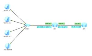
You, as the network administrator, were tasked with providing access to a network, where 4 machines have been connected.

It is simple task. Nothing can happen, but…

Everything is ready and you are checking connectivity between RT2 and those machines, and… To your suprise, you can only ping even-numbered IP addresses:

[RT2]ping 192.168.10.1
   PING 192.168.10.1: 56  data bytes, press CTRL_C to break
     Request time out
     Request time out
     Request time out
     Request time out
     Request time out

 [RT2]ping 192.168.10.2
   PING 192.168.10.2: 56  data bytes, press CTRL_C to break
     Reply from 192.168.10.2: bytes=56 Sequence=1 ttl=127 time=30 ms
     Reply from 192.168.10.2: bytes=56 Sequence=2 ttl=127 time=20 ms
     Reply from 192.168.10.2: bytes=56 Sequence=3 ttl=127 time=30 ms
     Reply from 192.168.10.2: bytes=56 Sequence=4 ttl=127 time=40 ms
     Reply from 192.168.10.2: bytes=56 Sequence=5 ttl=127 time=30 ms

 [RT2]ping 192.168.10.3
   PING 192.168.10.3: 56  data bytes, press CTRL_C to break
     Request time out
     Request time out
     Request time out
     Request time out
     Request time out

 [RT2]ping 192.168.10.4
   PING 192.168.10.4: 56  data bytes, press CTRL_C to break
     Reply from 192.168.10.4: bytes=56 Sequence=1 ttl=127 time=30 ms
     Reply from 192.168.10.4: bytes=56 Sequence=2 ttl=127 time=40 ms
     Reply from 192.168.10.4: bytes=56 Sequence=3 ttl=127 time=30 ms
     Reply from 192.168.10.4: bytes=56 Sequence=4 ttl=127 time=30 ms
     Reply from 192.168.10.4: bytes=56 Sequence=5 ttl=127 time=30 ms

What has happend?

You are sure that IP addresses and GW of PCs are correct. Let’s look into configuration of RT1 and RT2:

[RT2]
 #
 interface GigabitEthernet0/0/1
  ip address 10.0.0.2 255.255.255.0 
 #
 ip route-static 192.168.10.0 255.255.255.0 10.0.0.1

[RT1]
 #
 interface GigabitEthernet0/0/0
  ip address 192.168.10.254 255.255.255.0 
  traffic-filter inbound acl 3000
 #
 interface GigabitEthernet0/0/1
  ip address 10.0.0.1 255.255.255.0 

Everything seems to be OK. The only thing we should check is the access list number 3000. So let’s get to the ACL:

[RT1]display acl 3000
 Advanced ACL 3000, 2 rules
 Acl's step is 5
  rule 10 permit ip source 192.168.10.0 0.0.0.254 (20 matches)
  rule 15 deny ip (20 matches)

And we have a reason for the problem.

What is happening here? Let’s try to compare the IP address and the wildcard mask. Write them in binary:

11000000.10101000.00001010.00000000
00000000.00000000.00000000.11111110

We don’t care about the first 3 octects, as the bit in wildcard mask is 0. We have to focus on the last octet.

In our access list, the first seven bits of the last octet are all 1s. It means that the seven bits can be anything. The final bit in the last octet of our wildcard mask is 0. So, the very last bit in any IP address coming into this interface always has to be zero. The rest of the bits in that final octet can be anything.

What does this mean in practice?

It means that we can ping only IP addresses with the last bit 0. So we can only ping even-numbered IP addresses.

What if you want to ping only odd-numbered IP addresses. Nothing easier, just start the IP address in ACL at an odd number :

#
 acl number 3000  
  rule 10 permit ip source 192.168.10.1 0.0.0.254 
  rule 15 deny ip 
 #

Anyway, can you imagine the following wildcard mask: 0.0.255.0? What would happen if you used it with 10.10.0.1/24 IP address?

Finally you could have access to 10.10.0.1, 10.10.1.1, 10.10.2.1 and so on. How to use it in practice?

Assume that you use 10.10.0.0/16 subnet accross you entire network. You can split it to many /24 subnets. On each subnet there is a machine with the IP address 10.10.x.100 which is acting as a server offering the same functionality on each subnet. So you want to have access only to those machines, I mean 10.10.0.100, 10.10.1.100, 10.10.2.100…

To achive this goal, just configure the ACL like below:

 #
 acl number 3000  
  rule 10 permit ip source 10.10.0.100 0.0.255.0 
  rule 15 deny ip 
 # 

This article shows how powerful the wildcard mask can be. You can actually do interesting stuff with it, can’t you?

The post fun with wildcard mask on Huawei device appeared first on Labnario.


Huawei AR router USB-based deployment (ZTP)

$
0
0

USB-based deployment simplifies the deployment process. It reduces the deployment costs and relieves users from software commissioning. USB-based deployment allows you to configure or upgrade devices using a USB flash drive. Instead of having to visit all remote sites to commission those installed devices, it’s enought to prepare necessary files and let onsite personnel finish the deployment process easily.

Detailed information about USB-based deployment you can find exploring Huawei AR router documentation.

The post Huawei AR router USB-based deployment (ZTP) first appeared on Labnario.

The post Huawei AR router USB-based deployment (ZTP) appeared first on Labnario.

Viewing all 36 articles
Browse latest View live